GENERAL DESCRIPTION
The HL8048A is a single chip multifunction digital watch with heart pulse detector. With 128 LCD segment drivers, the HL8048A is programmed to provide 11 digits display. The heart pulse detector of HL8048A receives and amplifies the heart pulse signal from external photo sensor with a few external components.
Demonstration
(for people who live in China: Click here!)
FEATURES
HL8048B |
HL8048C |
| Digital clock and calendar | Digital clock and calendar |
| Up and down timer with alarm | Up and down timer |
| Step counter | Clock alarm and hour chime alarm |
| Distance display | EL driver |
| Calorie display | interference resistance |
| Target step display | heart rate calculation |
| interference resistance | AC Type Photo-sensing heart pulse detection |
| heart rate calculation | |
| AC Type Photo-sensing heart pulse detection |
ABSOLUTE MAXIMUM RATING
Supply Voltage (VDD to VSS) ------------------------- 6V
Input Voltage Range ------------------------- (VSS - 0.3V) to (VDD + 0.3V)
Operating Temperature Range ------------------------- 0℃ to +60℃
ELECTRICAL CHARACTERISTICS (VDD=4.5V, GND=0V, Ta=+25℃)
PARAMETER |
CONDITIONS |
MIN |
TYP |
MAX |
UNITS |
| Operating Current | Heart Pulse off, no LCD connected | 10 | uA | ||
| Operating Current | Heart Pulse on | 5 | mA | ||
| Operating Voltage | Figure | 3.3 | V | ||
| Input low voltage | PI0 ~ PI4 , PIO1 ~ PIO3 | 0.8 | V | ||
| Input high voltage | PI0 ~ PI4 , PIO1 ~ PIO3 | 2.2 | V | ||
| Output low voltage | Iout = -0.1mA | 0.5 | V | ||
| Output high voltage | Iout = 0.1mA | 2.5 | V | ||
| EMIT output current | VEMIT = 1.2V | 20 | mA |
PIN DESCRIPTION
PIN NAME |
FUNCTION |
| VDDD , GND | Positive and Negative inputs of digital power supply |
| VDDA , GNDA | Positive and Negative inputs of analog power supply |
| RVD | Regulated positive power supply output |
| EMIT | Photo Emitter driver |
| SENSI | Photo Sensor input |
| CI1 , CI2 | Input and output of sensor current Integrator |
| PSI , PSO | Input and output of pulse sample |
| A1IP , A1O | Positive input and output of first amplifier |
| A2IP , A2IN | Positive and negative inputs of second amplifier |
| A2O | Output of second amplifier |
| A3IN | Negative input of third amplifier |
| OSC1 , OSC2 | Input and output of crystal oscillator |
| PI0 ~ PI3 | Inputs of Mode , Set , Adjust , and EL Keys |
| PI4 | Pulse Key input |
| PIO1 | Input / output port 1 |
| PIO2 | Input / output port 2 |
| PIO3 | Input / output port 3 |
| EL1 ~ EL2 | Outputs of EL driver |
| BEEP | Output of Beeper |
| CAP1 | First voltage output of LCD driver |
| CAP21 , CAP22 | Second voltage outputs of LCD driver |
| CAP3 | Third voltage output of LCD driver |
| COM0 ~ COM3 | Outputs of Common drivers of LCD |
| SEG0 ~ SEG31 Outputs of Segment drivers of LCD | Outputs of Segment drivers of LCD |
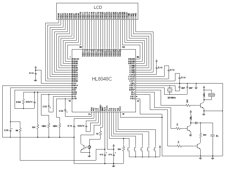
Figure: Application Circuit