HL7003-01 Speech Recognition
HL7003-02 Speech Recognition
GENERAL DESCRIPTION
HL7003 is a monolithic user dependence speech recognition IC designed for Toy Application. HL7003 consists of Microphone Amplifier, A/D Converter, Speech Processor, and I/O Controller. After pre-recording, HL7003 can recognize up to 12 different word sentences each with 1.5 sec long. With highly I/O programmability, HL7003 can be adapted in a wide range application for toy products.
FEATURES
- Built-in microphone amplifier
- Built-in A/D Converter
- Twelve 1.5 sec long word sentence
- Versatile I/O Ports:
- 2 general inputs
- 4 trigger inputs
- 2 output ports of
- 4 outputs
- 12 outputs
- 2 LED drivers
- Code option available for custom application
- 2.4V ~ 4.5V operation voltage
- Low power consumption
ABSOLUTE MAXIMUM RATING
- Supply Voltage (VDD to GND) ----------------- 5V
- Input Voltage Range ------------------ (GND- 0.3V) to (VDD + 0.3V)
- Operating Temperature Range ----------------------- 0℃ to +60℃
ELECTRICAL CHARACTERISTICS ( VDD=3V , GND=0V ,Ta=+25℃, unless otherwise noted )
PARAMETER |
CONDITIONS |
MIN |
TYP |
MAX |
UNITS |
| Standby Current | Shut down | 1 | 10 | uA | |
| Operating Current | Outputs no load | 2 | mA | ||
| Input low voltage | VDD=3V | 0.8 | V | ||
| VDD=4.5V | 1.2 | V | |||
| Input high voltage | VDD=3V | 2.2 | V | ||
| VDD=4.5V | 3.5 | V | |||
| Output low voltage | Iout = -0.5mA | 0.5 | V | ||
| Iout = -1mA , VDD=4.5V | 0.8 | V | |||
| Output high voltage | Iout = 0.5mA | 2.5 | V | ||
| Iout = 1mA , VDD=4.5V | 3.6 | V |
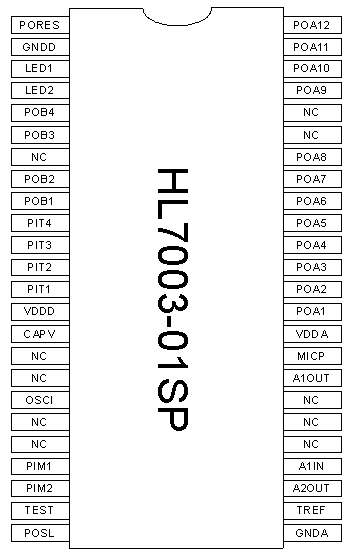
PIN DESCRIPTION
PIN NAME |
FUNCTIONAL DESCRIPTION |
| GNDD | Digital Ground pin |
| LED1 | Low active LED driver pin can be programmed to indicate voice input phase for standard application. |
| LED2 | Low active LED driver pin can be programmed to indicate the recognized result of input voice for standard application. |
| POB1 ~ POB4 | Output Port B, can be programmed as keypad scan drivers for standard application. |
| PIT1 ~ PIT4 | Low active Trigger Input Port, with built in pull high resistor, can be programmed as key in detector for standard application. |
| VDDD | Digital VDD pin |
| CAPV | Decoupling capacitor must be connected between this pin and ground for internal voltage regulator. |
| OSCI | Oscillator frequency control pin, a 56K-ohm resistor must be connected between this pin and ground. |
| PIM1 ~ PIM2 | General input pins can be programmed as mode control inputs for standard application. |
| TEST | TEST control pin for manufacture |
| POSL | Output mode selector for Output Port A, Output Port A is high active when POSL is pull high and is low active when POSL is pull low. |
| GNDA | Analog Ground pin |
| TREF | Threshold control pin for voice input |
| A2OUT | Output of second amplifier |
| A1IN | Negative input of first amplifier |
| A1OUT | Output of first amplifier |
| MICP | Positive power supply for electric microphone |
| VDDA | Analog VDD pin |
| POA1~POA12 | Output Port A, can be programmed as bank indicator for words recording and/or recognized target words. |
| PORES | High active input pin for chip reset externally. |
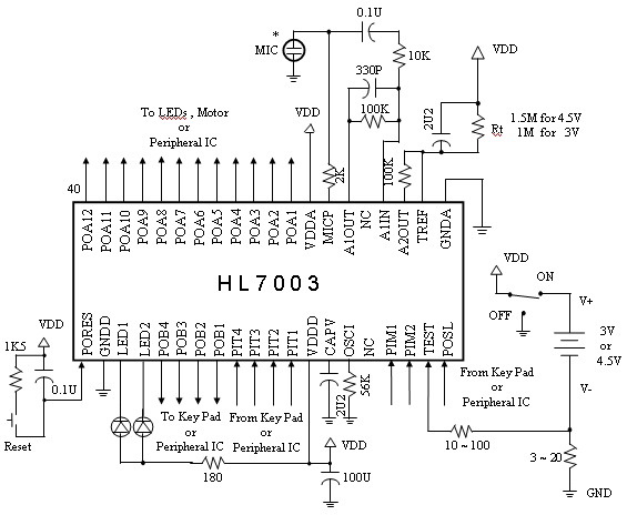
Application circuit
PIN CONNECTION DIAGRAM
SSOP 48 PIN