HL5313
GENERAL DESCRIPTION
HL5313 is a ToyID® interface tag IC that provide wireless interface between ToyID® reader and EEPROM or MCU. ISO/IEC 14443A standard reader can read or write HL5313 using ToyID® application program. Besides ISO14443A reader, HL5313 can also be accessed by HL5319 to form a low cost complete solution in toy. In the Tag there are three output pads that can be used to drive LED indicating communication status.
It also has 2-wire serial interface that can communicate with EEPROM or MCU. The EEPROM memories can be supported up to 8K bits. There is a RF detection function that output high to RFDET pad when RVDD exceed 2V. Besides, HL5313 can be shutdown to reduce power consumption by pulling down the ENB pin that only function in dynamic mode. There is an operation mode control pad. When this pad is high, HL5313 operate in dynamic mode which MCU control the 2-wire interface to read or write registers in HL5313. When this pad is low, HL5313 operate in static mode which HL5313 control the 2-wire interface to read/write EEPROM memories.
FEATURES
- RF interface data transfer rate: 106k bits/s
- Operating frequency 13.56MHz
- Support 4 and 7 bytes serial number
- RF signal detection function
- 2-wire serial interface
- Two operation mode; static and dynamic mode
- Static mode can address up to 8 k bits
- Dynamic mode operates with external controller
- Build in three LED drivers
ABSOLUTE MAXIMUM RATING
- Supply Voltage (VDD to VSS) ----------------------- 5V
- Input Voltage Range ---------------------------------- (VSS - 0.3V) to (VDD + 0.3V)
- Operating Temperature Range ------------------------ 0℃ to +60℃
ELECTRICAL CHARACTERISTICS
(VDD = 3.3V, GND = 0V, Temp=25oC, unless otherwise noted.)
| SYSTEM | CONDITIONS | MIN | TYP | MAX | UNITS |
| VDD | TENA , TENB =10V | 0.5 | 5 | uA | |
| IDD | DOUT no load | 420 | 650 | uA | |
| ILED | Source (DOUT = 9V) Sink (DOUT = 1V) | 2 2 | 5 5 | mA | |
| ICO | Rosc = 1.5M Ω Rosc = 1.0M Ω | 11 17 | KHz | ||
| VRD | 4 | 12 | V | ||
| TSU | |||||
| FOP |
BLOCK DIAGRAM
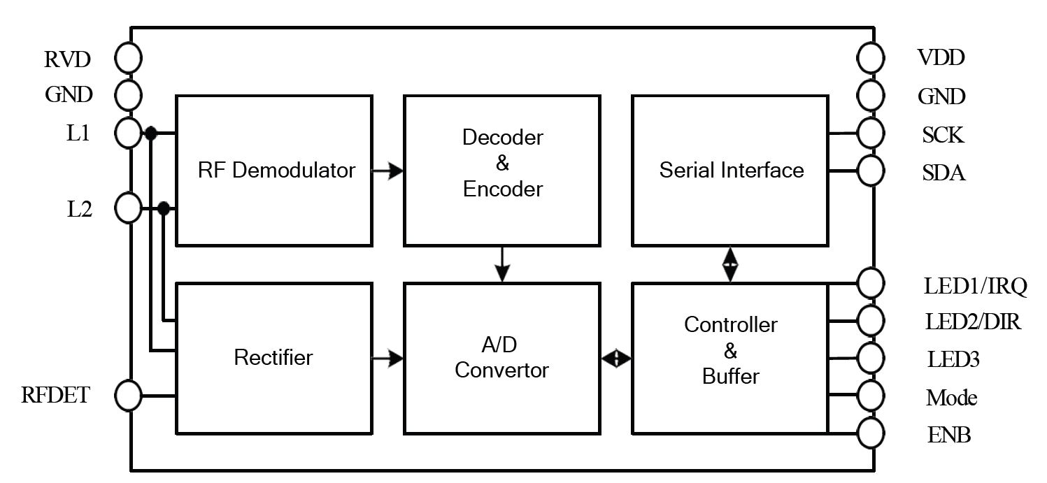
Figure 1: HL5313 Block Diagram
APPLICATION CIRCUITS
Static mode
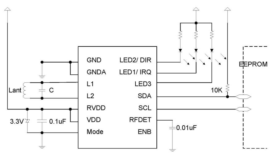
Figure 2: HL5313 Application Circuits A
Dynamic mode
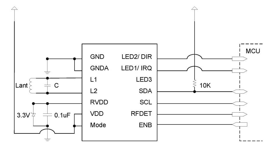
Figure 3: HL5313 Application Circuits B