GENERAL DESCRIPTION
HL5268-01 is a programmable 3 channel LED driver. There are 3 independent constant current controllers for each LED driver. Three independent PWM brightness controllers are used to control the 3 LED drivers simultaneously. A serial data input port is parallel connected with power supply.
FEATURES
- 3 channel LED driver
- 3 constant LED current controllers
- 3 PWM brightness controllers
- 2 wire serial data input system
APPLICATION
- LED Light Bar
- LED Decoration Lamp
ABSOLUTE MAXIMUM RATING
- Power Supply -------------------------- 5V
- Input Voltage -------------------------- (VSS -0.3V) to (VDD +0.3V)
- Operating Temperature ----------------- -40℃ to 60℃
- Storage Temperature ------------------ - 65℃ to 125℃
ELECTRICAL CHARACTERISTICS
| SYMBOL | DESCRIPTION | TEST CONDITION | MIN | TYP | MAX | UNITS |
| VDD | Supply Voltage | 3.2 | 4.5 | V | ||
| Vp | Data Pause Voltage | VDD=3.6V | 0.2 | V | ||
| ILED | LED Driver Current | VDD=3.6V , VO=0.6V , 25℃ | 6 | mA | ||
| IOP | Operating Current | VDD=3.6V | 20 | mA | ||
| Tp | Data Pause Time | VDD=3.6V | 50 | 500 | us | |
| Td | Data Interval | VDD=3.6V | 100 | 300 | us | |
| Tb | Data Block Interval | VDD=3.6V | 550 | 800 | us |
VDD=3.6V
OPERATION OF THE SYSTEM
The operation of HL5268-01 is controlled by the command data input to HL5268-01. LEDs connected to the three LED drivers of HL5268-01 will be turn on according to command mode of input data.
HL5268-01 is set at standby state when power on. It should keep HL5268-01 at standby state for a time period longer than 5msec before first command data is input to HL5268-01. The command data is input to HL5268-01 by modulating the voltage of power supply applied to HL5268-01. The command data consists five data blocks. The first data block is "START" data block, it is a single pause signal. The pause signal is a zero voltage for a short time period of about 100us. The second data block is "MODE" data block, it is a 3 bits data. The third, fourth, and fifth data blocks are "DATA1", "DATA2", and "DATA3" data blocks of 3 bits data. The data value of "MODE", "DATA1", "DATA2", and "DATA3" is represented by the number of pause in the data block. An 1 pause data block has data value of 1, and a 2 pause data block has data value of 2, and so on. For the data block which has data value of 0, the number of pause is 8. The minimum and maximum period between two adjacent pauses in the data block is 100us and 300us. The minimum and maximum period between two adjacent data blocks is 550us and 800us.
There are nine command modes for HL5268-01 to control the operation of display the three LEDs through the three LED drivers.
The first command mode is "Random Color Change 1", the data code is "0, 1, 1, 2" for "MODE", "DATA1", "DATA2", and "DATA3" data blocks. One of six LED colors of red, green, purl, blue, yellow, and white is randomly selected to display with 3 cycles of fast fade in and fade out for each input command.
The second command mode is "Random Color Change 2", the data code is "1, 1, 1, 2". One of six LED colors of red, green, yellow, blue, purl, and white is randomly selected to display with single fast fade in and fade out after the command is received. The next LED color to be display will be repeat changed as the following sequence of red, green, yellow, blue, purl, white, red, and so on.
The third command mode is "Assigned Fade In & Out", the data code is "2, d1, d2, d3". The LED color is assigned by the values of d1, d2, and d3 of input command data. The fade in and fade out of LED is display single time with normal speed for each input command.
The fourth command mode is "White Color Flash with Assigned Static Color", the data code is "4, d1, d2, d3". The white color LED will be flash display for a short time and static display LED with the color assigned by d1, d2, and d3 of input command data.
The fifth command mode is "Assigned Static Color", the data code is "6, d1, d2, d3". The LED will be static display with the color assigned by d1, d2, and d3 of input command data.
The sixth command mode is "Combined Flash 1", the data code is "7 , 1 , 0 , 0". The white color LED will be flash display for a short time and static display low bright LED with the color of red, green, purl, and blue sequentially.
The seventh command mode is "Combined Flash 2", the data code is "7 , 1 , 4 , 0". The LED will be flash display for a short time with the color of red, green, blue, and white sequentially.
The eighth command mode is "Random Static Color", the data code is "7 , 4 , 0 , 0". The LED will be static display with the color randomly selected from one of red, green, purl, blue, yellow, and white.
The ninth command mode is "Fixed Color Change ", the data code is "7 , 0 , 3 , 0". Six continue fast fade in and fade out LED displays are carried out with LED color selected from one of red, green, purl, blue, yellow, and white in a fixed sequence for each display.
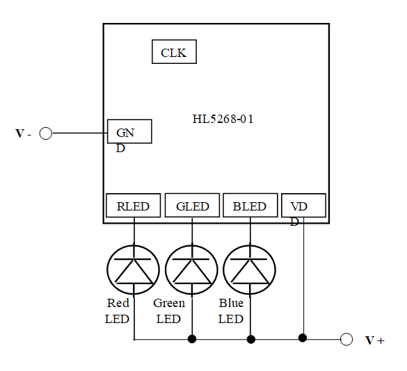
LED Connection Diagram
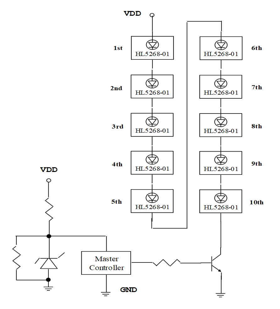
APPLICATION CIRCUIT I
Single Wire Cascaded Serial Connection
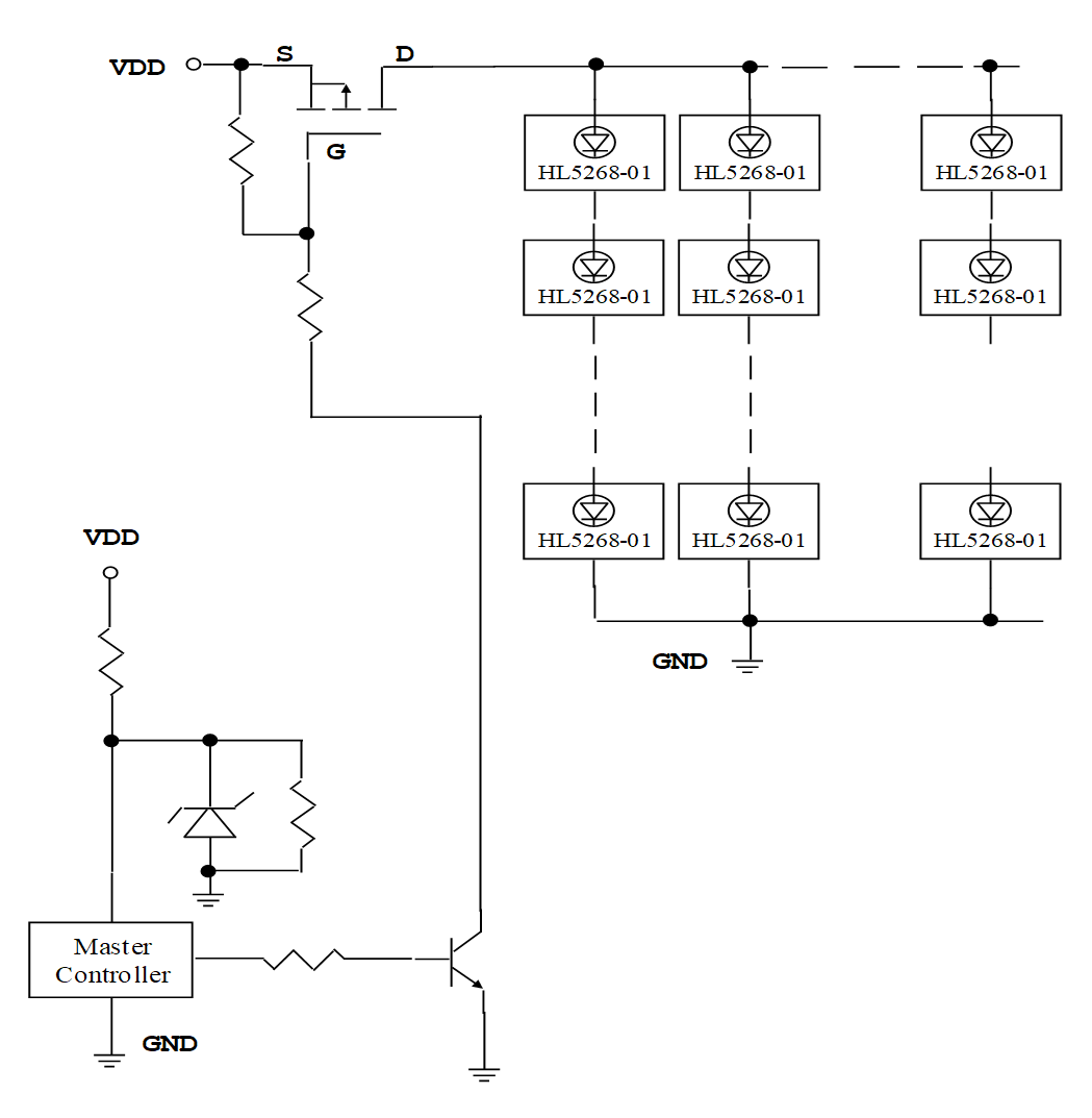
APPLICATION CIRCUIT II
Parallel Connected Multi LED String with Cascaded Serial Connection